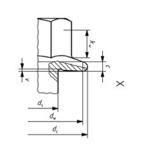
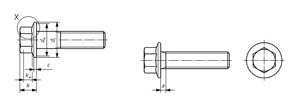
Screw head
Your use of this tool is entirely at your own risk.
We cannot take any responsibility or liability for any possible failures in your design.
The calculated output/results are approximate.
Choose the appropriate head friction value by clicking it in the matrix below.
Choose the appropriate thread friction value by clicking it in the matrix below.
Please choose between nut and tapped hole in order to obtain the material list to the right.
Choose the appropriate interface friction value by clicking it in the matrix below.
With this simple tool you can design the screw joint for your application and in addition get help with choosing a suitable assembly method.
The input values from your last session are automatically stored in a cookie.
Click 'Reset values' to delete your last input.
With this simple tool you can design the screw joint for your application and in addition get help with choosing a suitable assembly method.
The input values from your last session are automatically stored in a cookie.
Click 'Reset values' to delete your last input.
High strength joints are metric threaded joints with screws of property class 8.8 or 10.9. Also includes thread forming screws with a thread.
Low strength joints are non-metric threaded joints with self-tapping and in most cases case hardened screws made for plastic or sheet metal applications.
Dynamic high strength joints are joints where the external load is higher than 5% of the clamping force target value and where the external load stresses the joint more often than once per minute.
Static high strength joints are joints where the external load is higher than 5% of the clamping force target value and where the external load stresses the joint not more often than once per minute.
There are no specific criterias that have to be met in order to classify a screw joint as standard (regarding safety and/or legal criteria).
A classified joint has to fulfill certain safety and law criterias in order to be classified. It is mandatory that a safety classified joint must be monitored during assembly.
Description
Description
Choose a joint type from the examples below by clicking on one of the images.
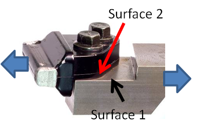
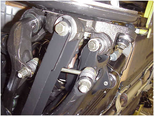
Standard static high strength joint
Standard static high strength joint. Transport loading bracket.
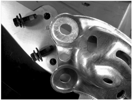
Classified static high strength joint
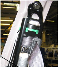
Classified static high strength joint. Safety belt attachment.
Standard dynamic high strength joint
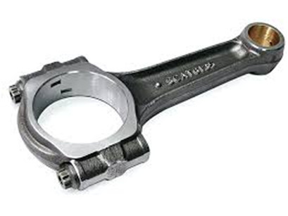
Standard dynamic high strength joints. For example, a connectiong rod or chassis joint.
Classified dynamic high strength joint
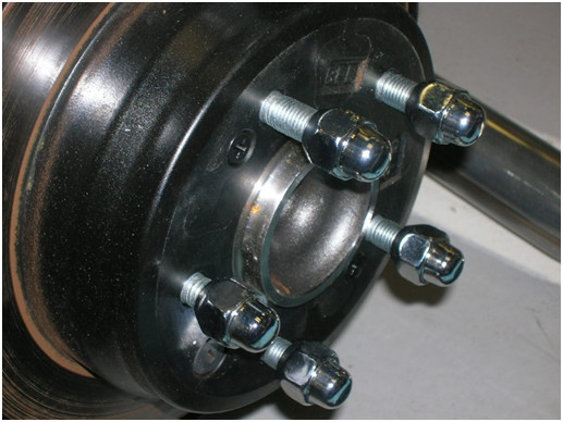
Classified dynamic high strength joint. Wheel screw joint.
Low strength joint screws
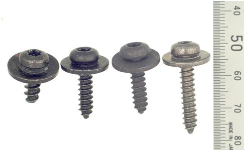
Low strength joint screws, used in sheet metal and plastic application.
Please read this document about Low strength joint design: Low strength joints guidelines
| Assembly inspection | Product audit | |
|---|---|---|
| Recommended control methods | Screw elongation measurements | Back to mark |
| Equipment | Length measuring gauge | Digital torque wrench |
The purpose with this test is to measure the torque needed to turn the screw after the joint has been assembled and relaxed (after static settlement). The value should be between the Upper Inspection limit (UIL) and the Lower Inspection Limit (LIL). Depending on the joint type these limits vary. For dynamic high strength joints the LIL value is normally higher than the LIL value for a static high strength joint.
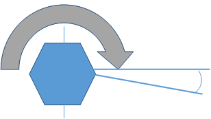
Turn the screw with continuous tightening less than 5 degrees.
Note the amount of torque needed. Put the value into your follow up system.
Tool: Digital torque wrench with top value hold and preferably gyro to help checking the angle.
| 1. Joint type | ||||||||||
| - | ||||||||||
| 2. Design | ||||||||||
| Dimension | ||||||||||
| Property class | ||||||||||
| Pitch | ||||||||||
| Number of screws | ||||||||||
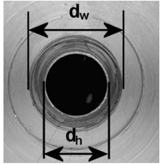
| Screw head, dw | ||||||||||
| Screw head, dh | ||||||||||
| Assembly friction Head | ||||||||||
| Assembly friction Thread | ||||||||||
| Clamping length | ||||||||||
| Material, clamped part | ||||||||||
| Minimal interface friction | ||||||||||
| Internal thread part | ||||||||||
| Type of load | ||||||||||
| Assembly torque | ||||||||||
| Loss in clamping force | ||||||||||
| Results calculation | ||||||||||
| Clamping force | ||||||||||
| Contact pressure | ||||||||||
| Static axial strength | ||||||||||
| Dynamic axial strength | ||||||||||
| Static shear strength | ||||||||||
| Dynamic shear strength | ||||||||||
| Screw length | ||||||||||
| 3. Assembly | ||||||||||
| Dimension | ||||||||||
| Property class | ||||||||||
| Prevailing | ||||||||||
| Type of joint | ||||||||||
| Clamping length | ||||||||||
| Assembly torque | ||||||||||
| Angle monitoring | ||||||||||
|
Assembly tool Results - assembly methods graph |
||||||||||
| 4. Inspection | ||||||||||
| External load | ||||||||||
| Assembly method | ||||||||||
Static external load in combination with yield point assembly is not applicable.
|
||||||||||